The OSU Mars rover team created and machined a robotic arm with 6-degrees of freedom about ~4 years ago. The design of the arm was inspired by the Universal Robot 5e arm. Prior to this project, the arm was controlled using a combination of an xbox controller, and UI buttons on the control station that would set the arm to certain predefined poses by driving each joint to a certain position. Encoders were used to determine the position of each joint. This was done using forward kinematics- a series of kinematic equations that define the position of the end effector (in cartesian coordinates) by using the movement of each joint in the chain the end effector is attached to. Code-wise, this was implemented using a ros node that subscribed to messages that specified each joint's position (using data from the encoders). Those values were then used to populate an array that stored the updated position of each joint. The hardware used for controlling the motors in the arm was the IONI stepper driver- which has a robust C++ library that allowed our ROS nodes to interface with them. I was not the one responsible for writing the code that controlled the arm using FK, that was written before I joined the team.
There were 3 main goals of this project: Reasearch different motion planning techniques/algorithms for inverse kinematics, implement simulation of the arm in RViz and Gazebo (ROS' inbuilt/preferred simulation and physics engine), work on writing and interface between the simulated/planned motion and the actual hardware controlling the arm. This was a multi-year proof of concept project with the eventual goal of linking hardware to the simulation, but due to hardware issues with the IONI stepper drivers, and comms issues with the wiring in the arm itself- the hardware interface between the sim and the IONIs was never able to be fully tested before I graduated.
The code for arm simulation was written for ROS 1 Melodic. It utilized the Moveit! ROS package by Piknik Robotics for the necessary plugins for trajectory planning/IK solving, and the ROS control package for implementing the hardware interface. Most of the work involved working on configuration files to work with the IK plugins and then writing the necessary code to use ROS Control to interface with the IONIs themselves.
Project contributions
I inherited this project my freshman year of college after learning the basics of ROS. I have always had a latent interest in working with animation and 3D modelling so arm project interested me. The first part of this project was to research the various motion planners within ROS and identify which one suited the team's needs best. The first part of this process was reading the available documentation on the planners as well as the associated research papers. As a freshman, reading these papers was a little overwhelming due to the math involved, but I ended up getting the broad strokes of the strengths and weaknesses of each planner. I ended up choosing between the planners provided by the OMPL (RRT Star and RPM star) and the Stochastic Trajectory Optimization for Motion Planning (STOMP) package. I won't go deep into the details of each library here, but I've linked the relevant documentation for each on the project's github page. By default, Moveit! utilized the OMPL planners. The OMPL planners are good for generating basic paths like moving the end effector along a line. STOMP is designed to create smooth paths in cartesian space by utilizing probabilistic optimization. I ended up working on integrating the STOMP planner into our already setup Moveit! configuration for our arm. I did this with the idea if the planning times were unreasonable or if the paths created weren't realistic- we could always fall back to using the OMPL planners, which had been tested prior to me starting on this project.
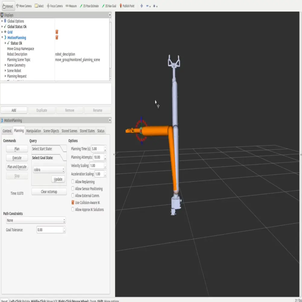
On the IK side of the project, there were two IK solvers to choose from: The IKFast Kinematics plugin and the TRAC-IK Kinematics solver. Both solvers improve upon the standard IK solver included in the KDL library for ROS 1, and both had their own strengths. I ended up implementing both for simulation and comparing them 1 to 1 to see which solver produced quicker planning and execution times when planning to move the arm to a preset position. The animation above is from one of the test runs. I should note, none of the IK project involved me writing my own IK solvers- that was not the purpose of this project. Rather it was to utilize and integrate existing plugins for IK solving to work with our specific robot arm. Most of the work for both the motion planner integration involved editing configuration files to represent the specific parameters and joint limits on our arm to produce an accurate simulation.
The bulk of coding work I did for this project was during my sophomore year of college. This was the work to connect the simulation to the physical arm. Within ROS there is a library called ROS Control. Controlling robots using ROS Control consists of two parts- the controller itself and the hardware interface. The controller is responsible for receiving goals from the simulation in either effort (voltage), velocity, position, acceleration, or a combination of these and then working with the hardware interface to actually command the joints/actuators of the robot to the goal. The hardware interface itself is responsible for writing these goal states directly to the hardware and also reading the current state of the robot from the hardware. Hardware interfaces are custom to each robot, but the ROS control library provides standardized boilerplate code depending on what type of goals you're trying to send to the robot. The controller itself the end user does not have to write, but the boilerplate for the hardware interface has to be edited to work with each specific robot.
For our particular robot arm I chose to implement the joint-trajectory controller and a position-based hardware interface. The joint-trajectory controller in ROS control is good for controlling a group of joints and represents the transition from the current state of the robot to the goal state as a series of waypoints. I.e if we wanted to move our end effector along a linear trajectory- the joint-trajectory controller would take in the planned goal state from our simulation and then generate a series of waypoints to move the end-effector from point A to point B. On the hardware interface side of things, I implemented a position based hardware interface. In practice that means the hardware interface was responsible for reading in current position data from the IONIs and writing the positional data generated by the controller back to the hardware. This hw interface was chosen because it was one of the simplest to implement- other types required knowledge of setting proper gains for PID control that I didn't have at the time.
The IONIs themselves use a C++ library called SimpleMotion for read/write purposes- so the majority of the work this part of the project was integrating the IONI specific functions into the boilerplate position hardware interface provided by ROS control. ROS control was an entirely C++ based package in ROS 1, so all the code I wrote for this project was in C++.
While I was working on writing the hardware interface and getting the associated ROS control package implemented into our software stack- the arm itself suffered massive electrical damage. This meant the actual simulation/ROS control interface wouldn't be able to be tested with the arm until the electrical damage was repaired. To combat this- I looked into ways to use the joint limits set by the URDF with a simulated hardware interface- and then test motions in the Gazebo physics engine to validate planned paths actually obeyed these joint limits. I ended up writing a position-based hardware interface that implemented perfect feedback- meaning it only keeps track of the previous and current goal states and ignores velocity. In the end, the simulator allowed for execution of paths outside of the proper joint limits- I was never able to figure out the cause of this.
Lessons Learned/Outcome
This project encompassed about two years worth of my time on the Rover team. I originally had partners in the project, and tried to recruit more members to share the brunt of the work but there were numerous obstacles preventing people from sticking with this project in the way I had. The first is that the university changed its CS cirriculum to not introduce C++ programming until sophomore year- meaning fresh members of the team did not have the necessary experience to work with the C++ libraries necessary for the arm. The second is that the documentation for ROS control in particular has always been sparse. This makes the learning curve associated with this project steep- I myself experienced a lot of frustration trying to find good resources explaining what is actually happening and how to implement controllers properly. It was very hard for me to make the topics approachable for people interested in the arm, especially when they were still trying to get a handle on the ROS ecosystem itself. It's been nice to see the documentation become more robust with ROS 2 and I am incredibly appreciative of the open source community that contributes to improving these tools.
Overall, this project really put my C++ skills to the test. Genuinely working on this project is probably the most I've ever utilized C++ in my life, and it was nice to put the skills I learned in the introductory CS courses into practice. Beyond that, this project really inspired my passion for robotics simulation. It is still an area the team lacks, and it's so important for not just the arm, but the Rover as a whole. The other neat thing about this project is it is a big portion of what landed me an internship at NASA JPL.
This project ended up being a proof of concept. I never ended up being able to test the ROS control link on actual hardware due to the arm being completely rewired. It ended up that the IONIs had serious electical damage and we were not able to get them properly diagnosed and implemented, even using the IONI specific carrier boards. In hindsight, I would have wanted to explore each motion planning algorithm more in depth- especially with how many different planning algorithms the OMPL provides. There are so many different areas of study that go into making robotic manipulators actually move, and I'm glad that this project exposed me to some of them. Although the hardware issues limited me from seeing this project to the completion I wanted to, going forward I would like to continue working in the robotic simulation sphere and also keep learning about control theory/control systems. Without taking on this project, I wouldn't have fostered an interest in these areas.